The importance of Recess Gaging in the Fastener Industry
Have you ever tried to drive a screw in a deck board only to get three quarters of the way down and suddenly you strip out the recess with the driver bit? If so, you either have a recess that is of bad quality or you have a driver bit of bad quality. The causes of this bad quality can be caused by many things,
- Poor metallurgical properties of the recess or driver bit,
- A recess that was not formed properly,
- A gage that is out of its specification therefore not in conformance to its design intent,
- A driver bit that is not formed properly.
All 4 of these failures can be prevented by having the correct gaging that is calibrated to standards and used according to their design intent. Early detection of these causes are as follows:
- Metallurgical failure is identified by torsional strength testing. This is accomplished on driver bits by using a driver bit test block. This test block is a precision-made fixture for holding the driver and using a torque tester. When engineers develop the specifications for the minimum torsional strength of a driver bit, they had to design a standard test block so that the strength capability data could be used to define a specification for an acceptable driver bit. Therefore, it is extremely important that the manufacturer knows what standard to use that defines the correct test block and know where to purchase the test block. This purchase should be from a known manufacturer who has the capability to certify the test block. See Illustration “A”
Driver Bit Test Block Fixture

Illustration “A”
2. When it comes to gaging the fastener recess, there are some very important gage requirements to be considered.
Cross Recess
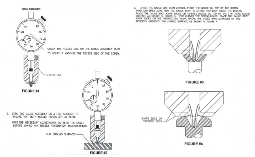
a. Penetration: recess penetration is defined by the depth a driver bit enters the recess and not the total depth of a recess. The penetration depth is gaged differently depending on the recess type being manufactured. We will discuss cross recess and HexLobe® recess. Cross recess penetration gaging is done by using a penetration gage that has as its tip a gage element. This gage element has very precise geometry that is profile ground and duplicates the recess itself. This enables the element to mate at a datum point within the recess and provides a depth at this mating point that is displayed on the indicator head. That resultant needs to fall within the specifications defined in the standard that is being manufactured. See Illustration (B)
Cross Recess Penetration Gage

Illustration “B”
b. Wobble: for the cross recess there is a gage that is used for identifying if the recess has the correct fit. Now, this can be done simply by taking a recess plug gage and inserting it into the recess and judge by feel that the fit is tight and should provide for a good driver bit to drive the recess. The wobble gage provides for quantifying the fit by inserting the plug gage into the recess and identifying the degrees of movement (see illustration (C) and ensuring that the resultant complies to the specification identified within the standard.
Wobble Gage

Illustration “C”
Hexlobe®
c. Penetration: As with the cross recess, the penetration depth is not the same as the overall recess depth. In both the cross recess and the Hexlobe ® there is a point at the end of the recess. The total recess depth is measured to the bottom of this point whereas the penetration is measured from the top of the recess to the intersection of the straight wall and the beginning of the point. See illustration (D). There is also another penetration type gage called the Fallaway gage. This penetration gage allows for a quantification of how far a no-go gage element enters a recess. Fallaway is important as it gages the the lead of the recess which ensures that there is a good lead that the driver bit can start into.
Hexlobe® Penetration Gage

Illustration “D”
Hexlobe®
d. GO NO-GO: the gaging of the Hexlobe ® recess is accomplished by using a GO NO-GO plug gage. The geometry of the recess has two diameters, an inscribed diameter, and a circumscribed diameter. The profile between these diameters is made up of many arcs. These gages are important to the manufacturer because it ensures the correct size of the recess as opposed to the penetration depth. The tolerance of the fastener, depending on the size of the recess can range anywhere from 0.003” (HL10) to 0.007 (HL55). The gaging elements tolerance is typically 0.0003” – 0.0006”. There are two types of gage elements, the final inspection, and the in-process. The sizes of the final inspection element are smaller than the In-Process element. The reasoning behind this is that the manufacturing operation uses the tighter tolerance which ensures that the final product meets the end specification.
3. Calibration of Gaging: the gages mentioned above need to be maintained and calibrated at a frequency defined by use. When calibrating a penetration gage it is not only important to calibrate the indicator but the gaging element as well. To calibrate either of the gaging elements listed above, very specialized measuring equipment needs to be used in an environment that is controlled for temperature and humidity. Optimally, the manufacturer will use a laboratory that is accredited to ISO17025. This standard ensures the competency of the laboratory to perform a calibration that falls within a certain measurement uncertainty. By doing this the manufacturer will greatly increase their ability to capably manufacture product at a high confidence level and minimize poor quality.
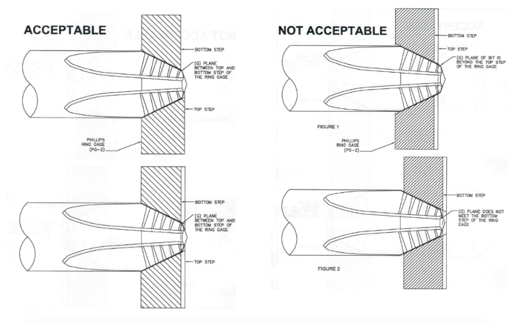
4. Driver Bit Gage: The driver bit gage is used for ensuring that the profile is within specification of the size driver bit being manufactured. Again, this gage is precision made and matches the cross-recess profile of the geometry opposite the external plug gage. The driver bit is inserted into the recess and the “G” width needs to fall within a 0.010” step built into the gage. See Illustration (F).
Driver Bit Profile (Ring) Gage

Illustration “E”
Summary:
As there are numerous fastener recesses in the world, the gaging concepts mentioned above typically apply the same gaging approach from a technical standpoint. The Wrentham Tool Group™ supplies not only the heading recess punches and pins but the recess gaging for each one. This gaging is manufactured on specialized equipment that can hold the tightest of tolerances here at the Bellingham, Massachusetts manufacturing facility. The company also has on site a calibration laboratory that is accredited to ISO17025 and Z540.3 by A2LA. This is important in that the gage specifications and tolerances for these gages are so small that not only environmental control is important, but the actual metrology applied needs to be consistent day in and day out.